Geometry miniaturization in fin-and-tube heat exchangers for refrigerant charge reduction
January 9, 2026

DOI: 10.18462/iir.icr.2023.0340
Stefano FILIPPINI*(a), Umberto MERLO(a), Dario DEMURTAS(a), Federico VOLONTÉ(a), Luca MOLINAROLI(b), Ennio MACCHI(b)
(a) LU-VE Group
Uboldo, 21040, Italy, [email protected]
(b) Politecnico di Milano
Milan, 20156, Italy, [email protected]
*Corresponding author: [email protected]
ABSTRACT
The indications given by the F-gas regulation and also the European Green Deal are contributing to the growing spread of small heat pumps that in many cases can be affected by flammability issues coupled with the use of natural refrigerants. Consequently, the market is looking for ever more efficient solutions to be achieved with very compact components, to reduce cost and refrigerant charge and to comply with safety constraints.
LU-VE has developed a new heat exchanger geometry specifically designed for small air-to-water heat pumps, giving significant advantages compared to the solutions currently available on the market. The adoption of a very small tube diameter, coupled with a fin shape optimized for this specific application through parametric CFD analysis, enables the ratio between thermal capacity and refrigerant charge to be increased by up to 40%.
An experimental campaign has been set up to validate the theoretical analysis, showing good matching both regarding heat transfer performance and air pressure loss.
Keywords: heat pumps, low refrigerant charge, air heat exchangers, CFD simulations
1. INTRODUCTION
The need to replace traditional HFC refrigerants has been well known for many years. These fluids are characterized by high Global Warming Potential (GWP), i.e. their contribution to increasing the temperature of the earth when released into the atmosphere is significantly high due to the greenhouse effect. Therefore the need to find new alternatives, encouraged by EU F-gas regulation 517/2014, has become ever more compelling: as a consequence, natural refrigerants (CO2, ammonia, propane) or synthetic fluids characterized by a lower GWP have permeated the refrigeration and, more generally, the HVAC&R markets.
A side effect of this replacement process arises from the flammability issue which characterizes many of these fluids, which are mostly classified as A2L (low flammable), A2 (flammable) or A3 (highly flammable), according to the rules of ISO 817:2014. Therefore the introduction of these fluids must be accompanied by a reduction of the overall refrigerant charge in HVAC&R systems according to safety standard IEC 60335: since fin-and-tube heat exchangers often contain a significative fraction of the overall plant charge, the reduction of the internal volumes while maintaining high heat transfer performance is a challenge that manufacturers must overcome.
So either for big plants or small applications the use of flammable fluids is increasingly popular. When retrofitting an existing system, large refrigeration plants (e.g. supermarkets or logistics centres) must reduce to a minimum the number of components to be replaced; A2L fluids like R454B or R455A represent a sort of obligatory choice, since CO2, which is almost a standard for new systems, requires a specific design of layout and components.
Nevertheless, the push given by the EU Green Deal to the spread of heat pumps to replace scrapped traditional fuel-powered boilers has been followed by a spread of flammable fluids also for residential small-scale applications (heating effect < 10 kW), replacing high-GWP fluids like R410A, since CO2 cannot be competitive either for cost and operating condition issues (the need for heat source temperature > 50 – 60
°C, i.e. very high operating pressures, incompatible with the requirements of a small applications).
Domestic dryers also represent an application which is nowadays characterized by the use of flammable refrigerants. The need of refrigerant charge reduction for safety needs can be easily understood and, even if the type of application seems to be different from standard air-to-water or air-to-air heat pumps, the inputs for the design of the heat exchangers share many common features.
2. FIN-AND-TUBE GEOMETRY MINIATURIZATION
2.1. Heat exchanger volume reduction: 4 mm tube diameter
Given the input described above from different sectors covered by its production, LU-VE has been working in recent years to gain significant volume reduction for its fin-and-tube heat exchangers. Continuing its history of being a pioneer in innovation and efficiency optimization, which enabled the successful release of heat exchangers with 5 mm tubes, the company invested new resources to continue its effort in this direction, resulting in the technological development of a new geometry, characterized by the use of a 4 mm tube diameter.
The design process started with the goal of maximizing the ratio:
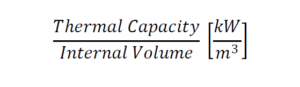 Eq (1)
Considering the existing 5 mm tube geometry as a baseline, many configurations were simulated and compared. Keeping the frontal area of the heat exchanger constant to guarantee perfect compatibility with the previous solution, different arrangement in terms of tubes and row pitch were tested. The best solution is a 20 x 17.3 mm geometry which, depending on the size of the row, can achieve an increase of P/V ratio up to 50%.
Let us consider the case of small air cooled condensers, such as the LU-VE Minichannel range, currently available with 5 mm tube geometry 20 x 17.3 (i.e. with tubes pitch 20 mm and rows pitch 17.3 mm). If we simulate the thermal capacities with the different geometries according to Standard Condition SC15 (i.e. Air inlet Temperature 25°C, Ref inlet Temperature 60°C, Ref condensing Temperature 40°C), we obtain the results summarized in the following graph (Fig. 1), where T5 refers to solution with 5 mm tubes, T4 refers to solutions with 4 mm tubes, with different tubes and rows pitch:
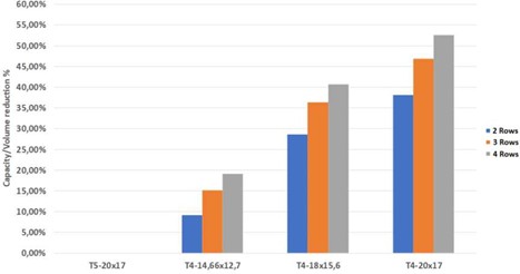
Figure 1: Capacity/volume reduction % – R290 Condenser (micro-finned tubes)
Similar results can be found when simulating the performance of the heat exchangers operating as evaporators. In this case the calculations were made considering Standard Condition SC2 (i.e. Air inlet Temperature 0°C, Evaporation Temperature -8°C, DT superheating 5.2 K). Even if this is a condition more characteristic of refrigeration applications, the outcomes summarized in Fig. 2 are perfectly transposable also for heat pump application.
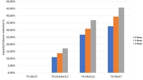
Figure 2: Capacity/volume reduction % – R290 Evaporator (micro-finned tubes)
2.2. CFD simulations for fin shape optimization
Once the layout of the geometry in terms of main dimensions (tube diameter, tubes and rows pitch, fin spacing) was defined, a CFD simulation activity was set up and carried out to optimize the shape of the louvered area of the fins.
The modelling of the fin is the result of a long history of CFD simulations gained in more than 20 years of experience and collaboration with experts from Politecnico di Milano. Symmetry and periodicity features help to reduce the domain to be meshed for the simulations: the minimum configuration that is usually considered consists of a 2-row portion of a fin having a width equal to half of the tubes pitch (see Figure 3). Symmetry conditions are applied on the fin plane to simulate the behaviour of a real extended fin, while periodicity conditions are applied on the direction perpendicular to the fin plane to simulate the presence of multiple fins. A proper volume of air is modelled around the solid fin and on inlet and outlet side.

Figure 3: Fin modelling example
Focusing on fluid behaviour between two coupled fins, Figure 4 shows the contours of the air speed on different planes varying the quote. These contours contributed to a better understanding of how to improve the heat transfer process and reduce the air pressure drop, defining the best shape of the louvers. In particular, it was noticed that the high-speed wakes rising adjacent to the tubes are disturbed by the presence of large louver. If this is avoided, there is a strong increase in pressure drop with a slightly increase in heat transfer coefficient. The width of the louvers has thus been limited, gaining further promising results.
![Velocity contour[m/s] on different planes between two coupled fins (z=0: mid-plane).](https://lu-ve.com/wp-content/uploads/2026/01/Geometry-miniaturization-Picture4.jpg)
Figure 4: Velocity contour[m/s] on different planes between two coupled fins (z=0: mid-plane).
Furthermore, in order to optimize the shape of the louvers among different working conditions and air speeds, a parametric model was developed to perform multiple simulations varying geometrical dimensions such as the width of the louvered area and the tilt angle of the louvers.
These simulations allowed the fin shape to be optimized, gaining an increase in heat transfer capacity over 3% compared to the previous configuration designed for 5 mm tube geometry. The exact geometrical dimensions determined through this analysis are omitted for confidentiality reasons.
The following characteristic parameters of the louvers were varied:
- Tilt angle of the louvers (i.e. height of the louvers)
- Width extension
- Number of rows of the coil
These configurations were analysed at three frontal air speeds: 1, 2 and 3 m/s. The study shows that there is an optimum solution for each layout of the exchanger. For example, the height of the louvers depends on the pitch of the fins (the greater the pitch, the greater the optimal height) and the same is true for the speed of the air and the number of rows of the coil. Given that the press for the construction of the fins must always be the same due to obvious technical and economic reasons, it is necessary to find the right compromise.
To evaluate the various solutions and build a ranking of the optimization results, a proper Merit Index was defined, taking into consideration the heat transfer coefficient and the air-side pressure loss across the fins. According to the experimental experience and considering some representative flow-pressure curve of common axial fans, the Merit Index has been defined according to Eq (2):
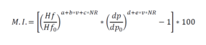 Eq (2)
Where:
- 𝐻𝑓 is the air-side heat transfer coefficient
- 𝐻𝑓O is the air-side heat transfer coefficient of the baseline configuration
- 𝑑𝑝 is the air-side pressure loss
- 𝑑𝑝O is the air-side pressure loss of the baseline configuration
- 𝑁𝑅 is the number of rows of the coil
- 𝑣 is the frontal air speed across the coil
- 𝑎, 𝑏, 𝑐, 𝑑, 𝑒, 𝑓 are numerical coefficients calibrated with LU-VE laboratory experimental experience
An overview of the different outcomes resulting from the performed simulations is shown in the qualitative charts in Figure 5. The numerical values are omitted for confidentiality reasons.
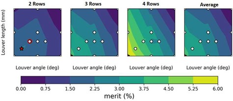
Figure 5: Parametric optimization map @ 2 m/s Air speed
Once the best configuration according to the Merit Index was identified, some further analysis was carried out to guarantee clear understanding of the fin and its fluid-dynamic interactions. Figure 6 shows the static pressure and temperature contours of the optimized fin on its symmetry plane.
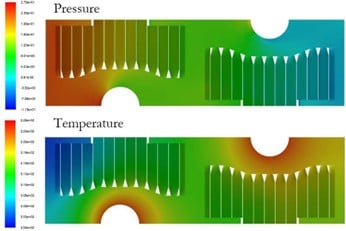
Figure 6: Pressure and Temperature contours on fin plane of symmetry
3. EXPERIMENTAL ACTIVITIES
To validate the preliminary theoretical studies, an extensive experimental campaign was carried out, aimed at defining the performance of the fins, the grooved tubes and the exchanger in its entirety.
The 4 mm diameter copper tube is among the smallest used for the construction of fin-and-tube heat exchangers: LU-VE, as per its tradition, has always opted for very small exchange matrices, which have various advantages, both in terms of performance and cost. However, building air heat exchangers with such small tubes requires considerable precision and careful manufacturing. LU-VE experience was really helpful in this sense, in order to obtain correct rolling, capable of minimizing the thermal contact resistance, while maintaining a good height of the micro-fins inside the tube.
To verify all the technological processes of coils construction, various tests were carried out in the aerodynamic tunnel. During the tunnel tests, the pressure drops on the air side and the heat transfer coefficient on the fin side are determined.
The experimental data comply with the theoretical data and indeed, a slight performance improvement was also obtained.
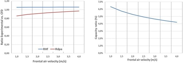
Figure 7: Comparison between CFD simulations and experimental measurements
To complete the experimental activity, tests were carried out on condensers operating with HFC refrigerant.
Figure 8 shows a summary of all the tests performed, reporting the capacity deviations as function of the deviations of the refrigerant pressure loss between the calculated data and the experimental ones.
This graph is very encouraging, showing the reliability of the performance prediction of the fin-and-tube heat exchangers manufactured with 4 mm tube. The deviations of the thermal capacities calculated by the LU-VE calculation method are within ±3%, while those of the internal side pressure drops are within ±6%.
Even if the condenser was tested using HFC refrigerant R507A, the results can be easily transferred to R290 or other flammable fluid.
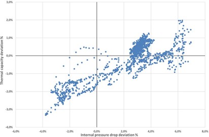
Figure 8: Condensers experimental deviations
4. HEAT PUMP REFRIGERANT CHARGE CALCULATION
Finally, the advantages of the use of low diameter tubes in the evaporator of heat pumps that operate with flammable refrigerants is assessed.
To this end, a small air-to-water heat pump working with R290 is considered and the charge of this system in the design condition is calculated under three different scenarios for the evaporator: 4, 5 and 7 mm tube, the last being almost standard in small heat pumps. The heat pump is designed to supply 5.1 kW to a water flow rate that is heated from 30 °C to 35 °C when the outdoor air dry bulb temperature is equal to 7 °C (wet bulb temperature 6 °C). Real, commercially available components are considered for the compressor, the condenser and the evaporator resulting in the components listed in Table 1.
Table 1: main components of the air-to-water heat pump considered for the charge comparison
| Component | Heat pump with 4 mm tube evaporator | Heat pump with 5 mm tube evaporator | Heat pump with 7 mm tube evaporator |
| Compressor | Rotary compressor Variable speed Swept volume: 15 cm3/rev Rotational frequency: 20 Hz – 85 Hz Oil charge: 0.48 dm3 Oil type: POE68 | ||
| Condenser (plate heat exchanger) | Plate height: 154 mm Plate width: 26 mm Plate pitch: 1.06 mm Plate number: 26 | ||
| Liquid line | Length: 1000 mm Inner diameter: 10 mm | ||
| Evaporator (fin-and-tube heat exchanger) | Tube outer diameter: 4 mm Tube length: 600 mm Coil height: 600 mm Fin pitch: 2.1 mm Number of tubes: 30 Number of rows: 3 | Tube outer diameter: 5 mm Tube length: 600 mm Coil height: 600 mm Fin pitch: 2.1 mm Number of tubes: 30 Number of rows: 3 | Tube outer diameter: 7 mm Tube length: 600 mm Coil height: 600 mm Fin pitch: 2.1 mm Number of tubes: 24 Number of rows: 3 |
The charge in the compressor is calculated considering the amount of refrigerant dissolved in the lubricant and considering the solubility diagram provided by the compressor manufacturer. On the other side, the charge in the evaporator is calculated adapting a finite volume model previously developed for the condenser simulation to the evaporator case (Joppolo et al., 2015) and using the Steiner version of the Rouhani-Axelsson void fraction model (Steiner, 1993). Similarly, the charge that the plate condenser holds is computed simulating this heat exchanger with a finite volume model like that of the evaporator, that uses the Smith correlation for void fraction (1969) as suggested by Mancini (2019). The results are reported in Table 2.
Table 2: charge estimation for the air-to-water heat pump considering three different evaporators
| Component | Charge | ||
| Compressor | 94 g | ||
| Condenser | 13 g | ||
| Liquid line | 37 g | ||
| Evaporator | 4 mm tube 48 g | 5 mm tube 86 g | 7 mm tube 153 g |
| Overall | 192 g | 231 g | 298 g |
The advantage of the use of a low diameter tube from the charge point of view is evident. Indeed, the use of a 4 mm tube results in a reduction of the charge of the heat pump which is around 17% (39 g) compared to the 5 mm tube and around 36% (106 g) compared to the 7 mm tube, i.e. the most widespread solution currently adopted. Although the charge is higher than the current threshold value, i.e. 150 g, the reduction is very significant and helpful in improving the safe use of flammable refrigerants.
5. CONCLUSIONS
The reduction of the environmental impact of HVAC&R systems is nowadays a must for every player in the global market. When dealing with natural or synthetic refrigerants with a low GWP but characterized by flammability issues, the reduction of internal volume of the heat exchangers becomes a central goal to be achieved. Indeed, the safety of people cannot be neglected just to achieve any global target; on the contrary, the challenge of producing systems which are safe, cheap and eco-friendly must be a priority in every company’s agenda.
The new fin-and-tube heat exchanger geometry with 4 mm tube diameter presented in this paper allows a decrease in internal volume of up to 50% to be achieved compared to the best solution currently available on the market. Thanks to optimization through CFD simulations, a further 3% in heat transfer performance has been achieved. The theoretical outcomes have been validated with an experimental activity, showing successful results.
The adoption of this new geometry for the construction of fin-and-tube evaporators in a small air-to-water heat pump for residential application can thus achieve a refrigerant charge reduction up to 36%, compared to current market solutions.
ACKNOWLEDGEMENTS
A particular acknowledgement is dedicated to the Energy Department of Politecnico di Milano, in particular to the professors and researchers who contributed with their knowledge and experience to the good success of the activity presented in this paper.
NOMENCLATURE
| p | pressure (kPa) | dp | Air side pressure drop (Pa) |
| T | temperature (K) | v | Frontal air velocity (m/s) |
Hf Air side heat transfer coefficient (W/m2K)
MI Merit index (%)
NR Coil row number
REFERENCES
EU Regulation 517/2014 of European Parliament and the Council on fluorinated greenhouse gases ISO 817:2014 – Refrigerants – Designation and safety classification
IEC 60335-2-104 (2021): Household and similar electrical appliances – Safety – Part 2- Particular requirements for appliances to recover and/or recycle refrigerant from air conditioning and refrigeration equipment
ASTM E681-09 (2015): Test method for concentration limits of flammability of chemicals
EN 327 (2014): Heat exchangers – Forced convection air cooled refrigerant condensers – Test procedures for establishing performance
EN 328 (2014): Heat exchangers – Forced convection unit air coolers for refrigeration – Test procedures for establishing the performance
Joppolo, C.M., Molinaroli L., Pasini, A., 2015. Numerical analysis of the influence of circuit arrangement on a fin-and-tube condenser performance. Case Studies in Thermal Engineering 6, 136–146
Mancini, R., 2019. Design and performance analysis of plate heat exchangers for heat pumps using pure and mixed refrigerants. PhD thesis, Danish Technical University.
Smith, S.L., 1969. Void fraction in two-phase flow: a correlation based upon an equal velocity head model. Proceedings of the Institution of Mechanical Engineers 184, 647-664
Steiner, D., 1993. Heat transfer to boiling saturated liquids. VDI Heat Atlas
Featured news
Latest news

Financial highlights as at June 30, 2026
")
Stainless steel casing option extended to cover the complete range of Alfa Optigo air coolers
")
A new Spare Parts hub