New generation of low-GWP refrigerants
January 8, 2026

19th European Conference | 10-11 June 2021 The Latest Technologies in Refrigeration and Air Conditioning
From January 1, 2021, the fluorinated greenhouse gases (F-gases) phase-down program, introduced by European regulation 517 of 2014, entered its third stage. Starting from this year, the quantity of tons of equivalent CO2 that can be imported into the European Union market in the form of fluorinated gases is limited to 45% of the average value of the three-year period 2009-2012 (baseline).
High GWP (global warming potential) refrigerants erode a higher portion of the available share than lower GWP refrigerants, effectively limiting the absolute quantity of HFC / HFO (kg) that can be imported into the market.
The air conditioning and refrigeration markets are heavily affected by this limitation. Lately we have been witnessing the forced transition from widely used refrigerants (R404A in refrigeration, R410A in air conditioning) towards blends of HFCs and HFOs with lower GWP.
At the start of the phase-down program, the total quantity of fluorinated greenhouse gases (kg) used in the European Union market had an average GWP of 2250. If we want to continue using the same quantity during this period of gradual reduction, we should reduce the average GWP to around 1000 from the beginning of this year (1 January 2021).
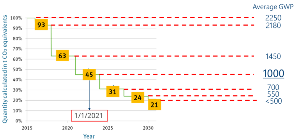
Picture 1: EU 517-2014 F-gas phase-down program and average GWP
HFC / HFO low-GWP blends
In this scenario, there are mainly two alternatives to prevent the share of tons of CO2 equivalent (in the form of fluorinated gases) available in the European Union market from becoming a limit on the diffusion of vapor compression refrigeration and air conditioning systems. The first involves abandoning fluorinated gases and moving in the direction of natural refrigerants which, at the moment, are not subject to regulations of this kind. The second alternative assumes that fluorinated gases continue to be used, but that we move towards blends with lower GWP.
Due to the nature of blends, these refrigerants have a temperature glide which in some cases can be very large. It is essential to understand the behavior of a refrigerant with this characteristic when sizing and setting up a system correctly.
In the picture below, it is easy to appreciate how the alternatives to R404A (the most common fluid in refrigeration), which have GWP below the 1000 threshold, fall within the ASHRAE A2L safety classification of “mildly flammable fluids”
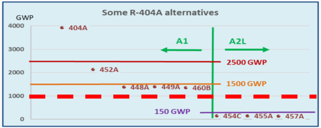
Picture 2: 400 series refrigerants and their characteristics
It is in fact possible to simplify the digression by saying that the low GWP fluorinated gases are mostly zeotropic mixtures with sometimes important temperature glide. In addition to that, the blends with the lower GWP (~ 150), are classified as mildly flammable (ASHRAE A2L).
A2L classified refrigerants require dedicated components and their use requires specific attention.
ZEOTROPIC BLENDS
The temperature glide of zeotropic mixtures influences the design and operation of the heat exchanger. In a zeotropic blend the composition of the liquid and vapor phase are different because the components have different boiling points. The component with the lowest boiling point evaporates earlier, the other component evaporates at higher temperature; as a result, the mean evaporating temperature will rise steadily over the two-phase range. The “glide” is the temperature difference between the bubble-point and the dew-point temperature at constant pressure.
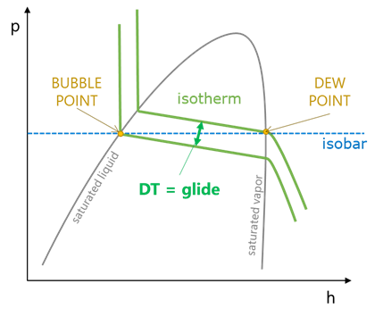
Picture 3: Pressure-enthalpy diagram of a zeotropic blend.
All refrigerants of the 400 series are zeotropic mixtures. In some cases (i.e. R404A), the temperature glide is very limited and in practice is ignored (these fluids are called near-azeotropic).
In the table below refrigerant data is reported for reference.
| Fluid | Components | Mass fraction | Critical temp., °C | Temp. glide, K @2 bar | GWP 100 years (AR4) | Safety group |
| R404A | R125/R134a/R143a | 0.44/0.04/0.52 | 72.1 | 0.7 | 3922 | A1 |
| R407C | R32/R125/R134a | 0.23/0.25/0.52 | 86.1 | 6.7 | 1774 | A1 |
| R410A | R32/R125 | 0.5/0.5 | 71.3 | 0.1 | 2088 | A1 |
| R448A | R32/R125/R1234yf/R134a/R1234ze(E) | 0.26/0.26/0.2/0.21/0.07 | 82.7 | 6.0 | 1387 | A1 |
| R449A | R32/R125/R1234yf/R134a | 0.24/0.25/0.25/0.26 | 82.1 | 5.6 | 1397 | A1 |
| R454A | R32/R1234yf | 0.35/0.65 | 81.7 | 5.7 | 239 | A2L |
| R454C | R32/R1234yf | 0.22/0.78 | 85.7 | 7.9 | 148 | A2L |
| R455A | CO2/R32/R1234yf | 0.03/0.21/0.76 | 85.6 | 12.6 | 148 | A2L |
| R457A | R32/R152a/R1234yf | 0.18/0.12/0.7 | 90.0 | 7.1 | 139 | A2L |
INFLUENCE OF TEMPERATURE GLIDE ON EVAPORATOR DESIGN
To explain how glide affects the evaporator design, let’s consider the following example.
- Operating conditions: Tair=0°C, Tevap=-8°C, DTsh=5.2K, Tliquid=30°C.
- Working fluids: R404A (DT glide ~0.7K, R455A (DTglide>12K).
In standard calculation, the evaporation temperature is considered at the dew-point. In fluid without (azeotropic) or with very limited glide (near azeotropic), the dew-point temperature is representative of the average temperature during the evaporation process (fig. a). If using a zeotropic blend with high temperature glide such as R455A, the average phase-change temperature is far below -8°C. As a result of this, the heat exchanger operates with much larger LMTD and the capacity increases significantly (fig. b).
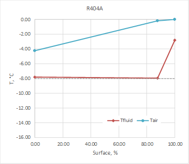
a) R404A, dew-point, DTsh=5.2K Capacity=2.36 kW
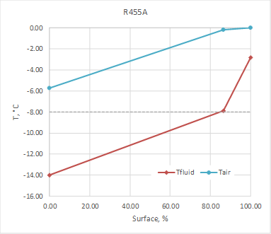
b) R455A, dew-point, DTsh=5.2K Capacity=3.21 kW
In order to do an equal comparison between the two fluids at equal average working conditions, the evaporation temperature at “mid-point” can be used in the calculation.
In this example, at -8°C mid-point evaporation temperature, the corresponding dew-point temperature for R455A is about -4.4°C. -8°C is the mean temperature that we expect to have between the beginning and the end of the evaporation process (fig. c).
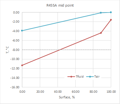
c) R455A, mid-point, DTsh=2.9K Capacity=2.17 kW
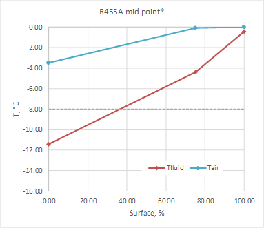
d) R455A, mid-point, DTsh=4K Capacity=1.93 kW
SUPERHEATING CONTROL
The capacity of a fin and tube evaporator is defined based on :
- Air inlet temperature: Tair,
- DT1 (difference between Tair and Tevap )
- Superheating: DTsh.
Usually a superheating of 0.65*DT1 is nearly the optimum value and it is specified by the EN 328 standard as the target value for evaporators. In our example: DTsh=0.65*8=5.2K.
In case of calculation at the dew-point this is straightforward. The temperature difference between the dew-point and the air entering the evaporator (counter-flow design) is always 8K. It is possible to set a DTsh of 5.2K and to obtain a reasonable temperature difference between air and refrigerant at the outlet, in the example 2.8K (see fig. a, b).
If using a calculation at the mid-point with high-glide refrigerant, the superheating is a critical aspect to consider.
In the calculation depicted in fig.c, a superheating is used considering as DT1 the difference between air and refrigerant dew-point temperature: DTsh=0.65*4.4=2.9K. In this way the minimum temperature difference between air and refrigerant is acceptable (1.5K) and the calculation is reliable. However, in practice, 3K of superheating is very challenging, the expansion valve control could be difficult and liquid droplets could reach the compressor.
In fig.d the same calculation is repeated with DTsh=4K. The minimum temperature difference with the air in this case drops down to 0.4K and the superheating requires more surface area penalizing performance.
Basically, in order to guarantee a superheating of at least 4K and an approach temperature (difference between refrigerant outlet and air) of at least 2K, a mid-point DT1 of 9.5K is required.
SAFETY ASPECTS TO CONSIDER WHEN USING A2L CLASSIFIED REFRIGERANTS
Using A2L classified refrigerants requires that some safety aspects are taken into consideration. The international standard IEC 60335-2-40 provides indications on the technical aspects of products that work with flammable refrigerants. A manufacturer of refrigeration or air conditioning components designed to work safely with A2L refrigerants must manufacture in compliance with the provisions of the IEC 60335-2-40 standard. The standard provides guidelines for correctly carrying out a risk analysis to ensure safety.
With a ventilated evaporator, the aim must be to ensure that there are no possible ignition sources in the event of a refrigeration leak. Two aspects must therefore be taken into consideration: the absence of voltaic arcs and sparks, and the certainty that there are no surface temperatures that could trigger combustion.
Concerning the phenomenon of arcs and sparks, it is necessary to correctly size all the electrical components and carry out experimental tests in particular on the fans, to ensure that what is prescribed is verified. Due to their construction characteristics, electronic fans are intrinsically safe, however it is necessary to use only models that have undergone specific tests.
On the topic of heat sources, we know that this problem directly involves the electrical defrosting elements (heaters) of an evaporator. The manufacturer of the product must carry out experimental tests to ensure that the maximum temperature reached by the defrosting elements is lower than the surface ignition temperature typical of each fluid, keeping a margin of 100 ° C, as per the regulation.
Recently, LU-VE Group has expanded its range of commercial unit coolers with the purpose of having in its portfolio units certified for the use of A2L refrigerants.
The redesign of the products and the certification have been carried out with a third-party independent organization and guarantee the safety of these new families using slightly flammable refrigerants.
Featured news
Latest news

Financial highlights as at June 30, 2026
")
Stainless steel casing option extended to cover the complete range of Alfa Optigo air coolers
")
A new Spare Parts hub